Description
Leonardo Diagnostic System Tool for (Ferrari, McLaren, Maserati and Lamborghini..etc)
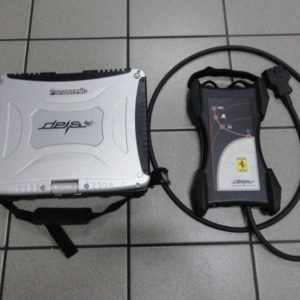
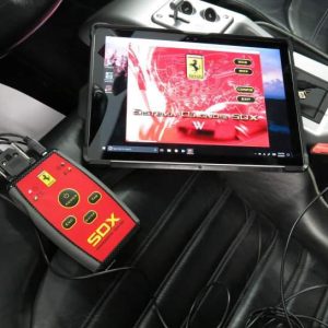
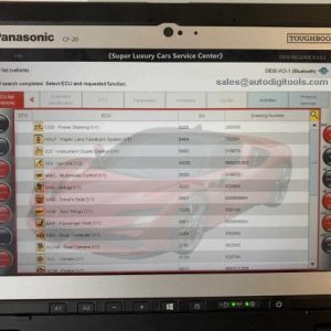
Leonardo is a professional diagnostic system of cars from Italy which has adaptation and coding function. It can diagnose models of Europe and Asia .Especially, it can diagnose the series brand of world famous Italian sports car, such as Ferrari, Lamborghini, Maserati.
Leonardo Tools: Newer, more advanced, supports Lamborghini, Ferrari and Maserati…etc with updated features.
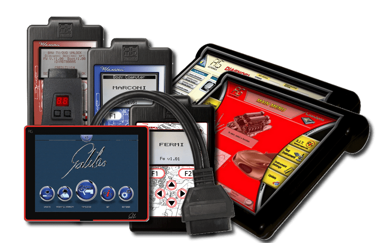
Compared with the official diagnostic tools, Leonardo has more features and functions, and it also can make up for the limitations that can diagnose only a single brand of models. While it is a highly cost-effective products and also preferred by many professionals.
Leonardo has a large bright **-inch touch screen and simple-to-use user interface, and also has Wireless diagnosis interface (Bluetooth) for remote diagnosis. Addition to basic diagnostic functions (read and clear fault codes, real-time read the data, diagnose and detect all electronic components, etc.), Leonardo also can achieve adaptation and coding functions.

General Specification:
1. Simple to use user interface, intuitive, complete with descriptive keys.
2. Separate unit with high speed connections, Bluetooth (class 1 with **0m range) or cable.
3. Human interface with *5 inch TFT LCD touch screen display, innovative compact design
4. Diagnostic interface with OBD vehicle plug and propreatary connectors (e.g. BMW, Mercedes, Fiat etc) with 5 inch TFT LCD touch screen with independent functions ( i.e. scan tool).
5. Diagnostics for all on board systems present on a vehicle and covering all the major car makes (Diagnostics through K-L line, J***0 and Can bus).
Diagnostics:
Automatic search and diagnostics of all on board ECUs (i.e. Mercedes E Class W**1 up to *5 settings) by pressing a single key (Fast Test Function).
On every electronic component the following can be carried out:
1. Reading and erasing errors.
2. Automatic display of Idendification, Hardware number, Software number and ECU manufacturer.
3. Reading of data in real time and displayed in numeric or graphic mode (up to 8 channels at the same time)
4. Check operation of components (i.e. electric windows, lighting, engine solenoid activation, etc.)
5. Adaptation and coding (reinitialize keys, ECU configuration, coding, recoding, programming ect.).
Programming ( on request):
Programming/Tuning ECUs using Millenium OBD II – Pro software, evolved from our Millenium Obd Tuning tool.
Measurements:
MULTIMETER:
( future implementation)
Reading of dc or ac voltage (voltmeter); Reading of resistive values (ohmmeter); Reading of dc or ac amperage (ampmeter); Continuity tester (components and cables).
DUAL CHANNEL OSCILLOSCOPE:
( future implementation)
AUTOSET Function on signals being measured; HOLD/RUN Function on displayed signals; *0KHz Analog band; Samples per second : **0.**0; Print the on screen data.
Technical Information System:
Simple to use database containing technical vehicle information.
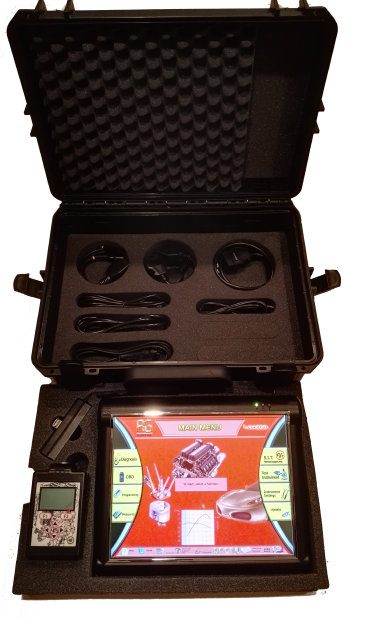
ACCESSORIES SUPPLIED
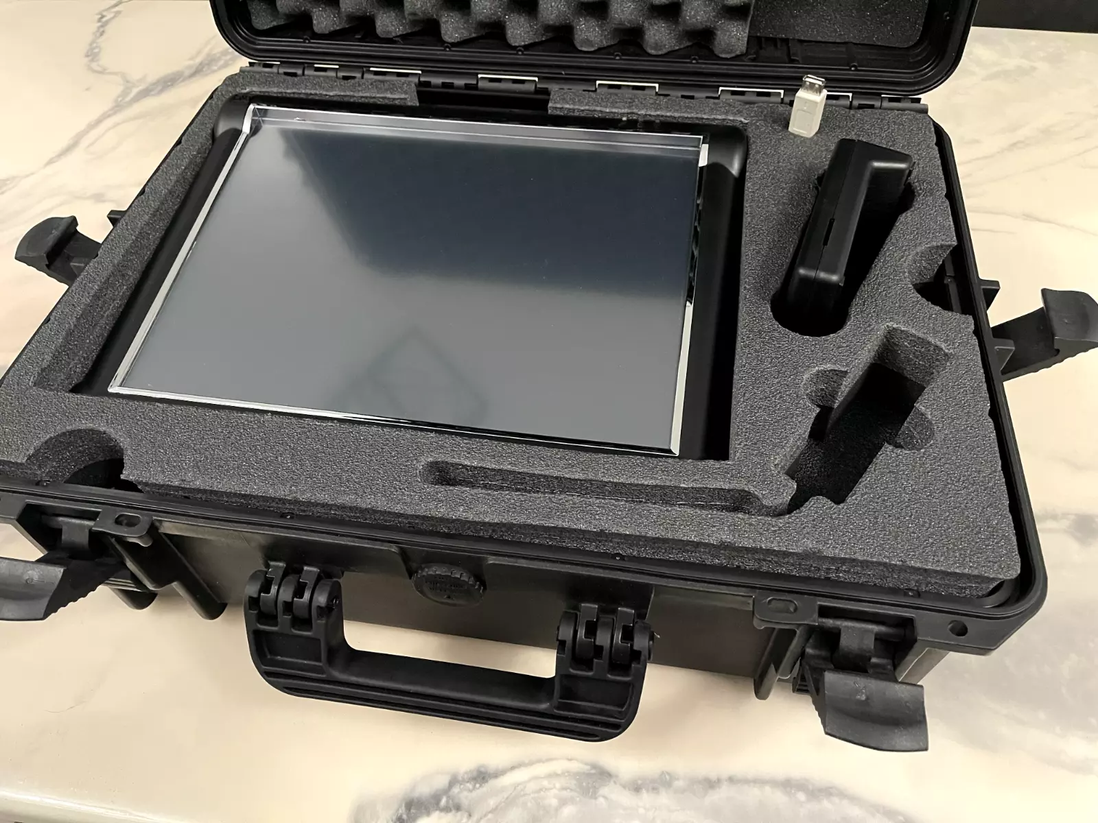
1. Impact resistant case with accessory housings.
2. Diagnostic cables kit.
3. Multimeter/oscilloscope cables kit.
4. In car power cable (cigarette ligher**2v)
5. Mains switching power supply/battery charger **0÷**0Vac *0÷*0Hz
Specifications:
POWER SUPPLY:
1. Mains using switching power supply/battery charger **0÷**0Vac *0÷*0Hz
2. In car *2÷*4 V;
3. Battery – over 2 hours.
DISPLAY:
1. LCD TFT *5” Touch screen – Resolution *******8 (Humaninterface)
2. LCD TFT 5” Touch screen – Resolution **0x**4 (Diagnostic interface)
DIMENSIONS: **0x**0x*0

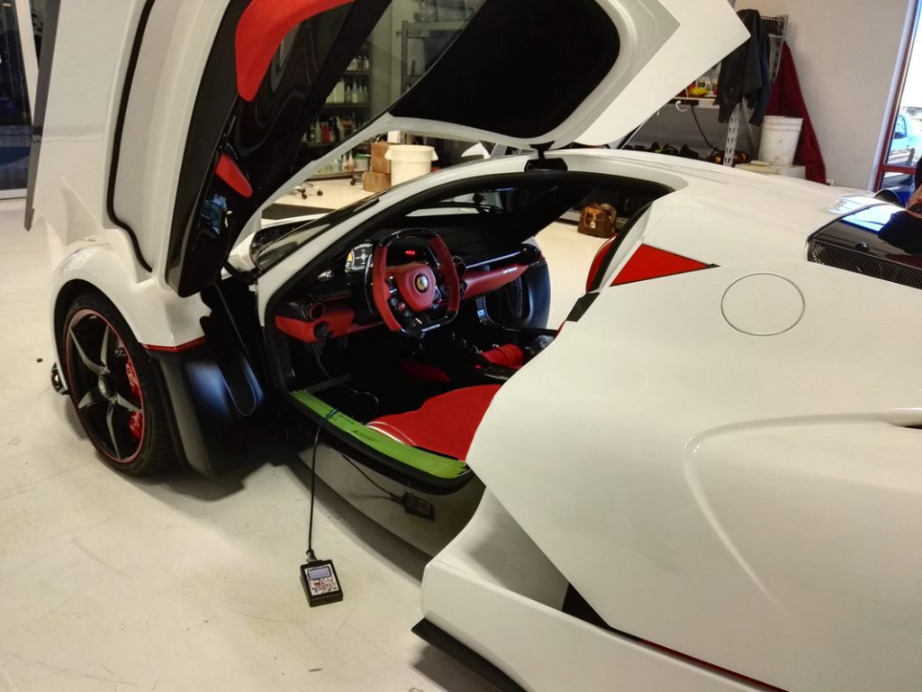
This Leonardo Diagnostic Tool is a trusted car scanner for Ferrari and McLaren car diagnostics. Exotic cars require the best and most comprehensive diagnostic car tools for their highly specialized systems. This Leonardo Diagnostic Tool offers dealer lever diagnosis along with Proxi Programming for Ferrari and McLaren.
CAUTION:
Before adjusting the gear shift / selection actuator system, the following checks must be carried out:
1. If the vehicle has been stationary for over 8 hours, it must be driven for *5 minutes in “Free Drive” conditions with repeated gear shifts.
2. If the vehicle has been stationary for more than *0 minutes, perform *0 consecutive pick-up manoeuvres, until reaching ***0 rpm.
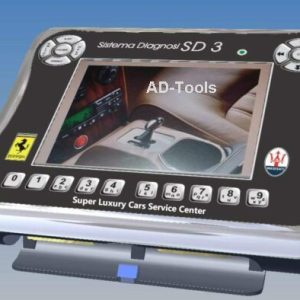
1) Switch on the SD3 and select the ” NCR KISS-POINT ” software option from the diagnosis programmes.
2) Select the ” KISS POINT ENVIRONMENT” function
3) The user is guided through the subsequent stages by the diagnosis system chosen.
4) Enter the vehicle serial number.
5) Use the TAB to select “CONTINUE” then press “ENTER” to confirm the data entered.
6) The system will display a warning message for the user, advising him/her of the vehicle conditions required to run the calibration procedure correctly.
7) If the vehicle meets the conditions which permit the procedure to continue, press “ENTER”.
8) Shift the gear to neutral, rotate the ignition switch to the OFF position, wait
9) approximately *5 seconds, then start the engine and select “ENTER” on the SD3.
*0) Select “START PROCEDURE “
*1) The following screen pages instruct the user to keep the accelerator pedal pressed throughout the entire data acquisition period.
*2) The system will carry out *0 clutch opening and closing cycles automatically, with the
*3) gearbox in the neutral position, during which the SD3 will acquire the data needed to calculate the touch point (PIS) correctly.
*4) Wait for the data acquisition procedure end message to appear on the display and a tone to be emitted by the instrument panel node.
*5) The SD3 will display the “TRANSMITTABILITY” graph, i.e. the current touch point (PIS)
position (in red) and the two references curves (in black) indicating the tolerance range within which the touch point curve must be located.
A = CSC bearing movement (Thousandths)
B = Torque (Nm)
*6) The system will automatically check that the touch point (PIS) curve read lies within the two tolerance curves.
*7) Two results are possible, depending on the outcome of this processing:
3. the data are correct and therefore the system will proceed with the next data acquisition stages.
4. the data are incorrect and therefore the procedure will be cancelled and an error message will be displayed with instructions for problem solving.
1) At the end of each data acquisition and processing sequence, the following parameters will be displayed:
2) Number of pick-ups (**3, **3, **3)
Touch point (PIS) value (bit,mm) (Min 6.*0 **0 bit, MAX **0 bit)
POINT SCATTERING value (Min 0 bit, MAX *0 bit)
3) If completed correctly, the procedure will be performed a further two times.
4) On completion of the three stages, the average touch point (PIS) value will be calculated and memorised by the gearbox ECU.
5) The message “TOUCH POINT (PIS) WRITTEN CORRECTLY will appear on the SD3 display.


